Rack & Pinion
A gear pair that converts rotary movement into linear travel along a straight axis.
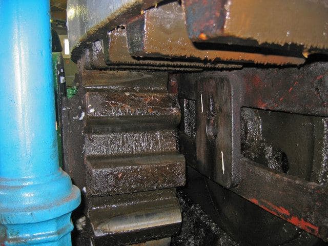
Illustrative reference image — not a Navora Precision product photo. Photo: Stephen Horncastle, CC BY-SA 2.0 via Wikimedia Commons.
What is it?
What is a rack & pinion?
A rack and pinion is a pair of parts that work together: a pinion (a small gear) meshes with a rack (a flat bar with teeth). As the pinion turns, its teeth push the rack along in a straight line — or, when the rack is pushed, the pinion turns. It is the standard way to get long, straight, controlled movement from a rotating input, which is why rack and pinion drives are used on machine axes, gantry systems, lifting platforms and steering mechanisms. The motion is simple, robust and easy to scale in length.
How does it work?
How it works
The pinion rotates; its teeth engage the teeth of the rack and push it along, so rotary movement becomes linear travel. The further the pinion turns, the further the rack travels — one pinion revolution moves the rack by one tooth circumference.
The pinion rotates → the rack travels linearly. Rotary input becomes straight-line motion.
Schematic only — not to scale, no specifications implied
Types & options
Common types
Common configurations include: Availability of any specific configuration is confirmed during engineering review.
Straight-tooth racks
Standard form for general linear drives
Helical racks
Angled teeth for smoother, quieter mesh
Round racks
Circular-section bar with axial teeth
Precision or application-specific racks
Ground or milled to the accuracy the application needs
Reference
Typical industry ranges
Commonly manufactured values for this component family. This is public engineering knowledge — not a statement of Navora Precision capability. What applies to your part — sizes, materials, tolerances, treatments — is confirmed against your drawing during engineering review.
- Common module range
- Module 1–10 in standard stock; finer-pitch ground racks for machine-tool duty
- Rack lengths
- 500 / 1,000 / 2,000 mm standard bars; longer travel from butt joints
- Common materials
- C45/EN8 carbon steel; alloy steel for hardened racks; stainless for corrosive environments
- Typical hardness
- Induction-hardened teeth ~45–55 HRC; case-hardened & ground racks up to ~60 HRC
- Tooth standard
- Involute profile per ISO 53; accuracy per ISO 1328 / DIN 3962
- Mounting
- Helical racks for crossed-axis drives; straight racks for parallel-axis; drilled & tapped fixing holes on request
Applications
Where is it used?
Generic application contexts for this component family (public engineering knowledge).
- Machine tool axes
- Gantry and portal systems
- Automation and robotics
- Elevating platforms
- Linear actuation
- Material handling
For the engineer
Technical considerations
The engineering questions that define a good requirement for this component family. These are general considerations — your specific values are agreed during engineering review.
- Gear geometry
- Module, pressure angle, helix angle and hand, and the number of teeth on the pinion define mesh behaviour and the linear travel per revolution.
- Travel & force
- Required travel length, axial force and positioning speed determine rack length and cross-section, pinion size and the duty the pair must handle.
- Load, speed & duty
- How hard the component works — forces, speeds, cycles per day — drives material, heat treatment and accuracy choices.
- Accuracy & tolerances
- Which dimensions are critical, and how tightly they must be held, determines the manufacturing route and the inspection effort.
- Mounting & interfaces
- How the part is fixed and what it mates with — shafts, housings, bolts, keys, chains — must be defined before manufacturing can be planned.
- Environment & surface treatment
- Dust, moisture, chemicals and temperature affect material choice, sealing and finishes such as plating, coating or painting.
- Lubrication & maintenance
- Whether the part runs in oil, grease or dry shapes clearances, material pairing and expected service intervals.
How to enquire
What helps us understand your requirement?
- The type of part or component
- Dimensions, or the drawing if you have one
- Material, if known
- Quantity or annual usage
- The application it goes into
- Operating conditions — load, speed, environment
- A sample or photo, if available
Don't have all of this? That's okay. Start with what you know — questions come back to you before anything is promised.
Looking for this component?
Discuss your component requirement
Share the parameters, the drawing or the sample — whatever you have. Engineering review comes before any commitment on either side.
Need something manufactured specifically for your application?
Explore Custom Manufacturing
Parts designed and manufactured around your function, envelope and interfaces — not a catalogue.